8-22mm Rear Mounting Kit.
Details and Installation Information
1) Orient the BareBones SS Display for Installation.
As shown in the illustration, flip the BareBones SS Display over and lay it on a flat, soft, non-abrasive surface to access the highlighted parts.

2) Remove Z-Bar Hanging Assembly, Cord Wraps, and Side Braces.
As shown in the illustration, using a #2 Phillips Head screwdriver, unscrew the (8) 8-32x1” pan head screws to remove the Z-Bar Hanging assembly, Cord Wraps, and Side Braces.

3) Install the 8-22mm Rear Mounting Kit.
As shown in the illustration, fasten the (8) 8-32x1” Phillips head screws (highlighted in RED) into the (8) 8-32 threaded inserts located on the rear of the BareBones SS Display which are also highlighted in RED. NOTE: DO NOT FORCE THE SCREWS INTO THE THREADED INSERTS OR OVER-TIGHTEN THEM AS YOU MAY DAMAGE THE DISPLAY. There are extra screws provided if neccessary.

4) 8-22mm Rear Mounting Kit Install Complete.
The 8-22mm Rear Mounting Kit when properly installed should resemble the illustration shown.

5) Retrieve and Orient the Piece the Display will be Mounted to.
As shown in the illustration, lay the piece you will be attaching the 8-22mm Rear Mounting Kit to on a flat, soft, non-abrasive surface.

6) Position the BareBones SS Display and Adjustable Stand-Offs.
As shown in the illustration, place the BareBones SS Display and the Adjustable Stand-Offs onto the work piece you are using from the step above. NOTE: Make sure the LED PANELS have been backed out enough within the 8-22mm Rear Mounting Kit so that the work piece you have selected stays flat on the work area you have set it down on. Refer to step 8 below regarding how to accomplish this.


5) Mark and Drill the Pilot Holes.
As shown in the illustration, Mark the holes where the mounting feet of the 8-22mm Rear Mounting Kit have been placed. Once marked, remove the parts and using a #44 or if unavailable a 5/64” drill bit, drill the pilot holes. NOTE: If the thickness of the work piece or board is 8mm, make sure to only drill as deep as to accomodate the included screws or other ones that you prefer to use. Also make sure to clear out any debris and sawdust, so that the screws will not push that towards the front of the work piece and create protrusions or breach the other side.

6) Fasten the Parts to the Work Piece.
As shown in the illustration, fasten the complete BareBones SS assembly and Adjustable Stand-Offs to the work piece using the included 4-24x3/8” sheet metal or preferred screws.


7) Locate the Height Adjustment Screws.
As shown in the illustration, locate the (8) height adjustment screws and the (2) for the Adjustable Stand-Offs if also installed.

8) Adjust the Height of the Display.
As shown in the animation, adjust the height as desired of the BareBones SS Display by slowly turning each of the (8) individual height adjustment screws. Turning in the CLOCKWISE direction lowers the display, turning in the COUNTER-CLOCKWISE direction raises the display. NOTE: Each adjustment screw should be turned no more than a couple of turns, followed by the remaining screws and doing the same thing until the desired height is reached. If you have also installed the Adjustable Stand-Offs, adjust the height of them as well so that the completed piece will sit parrallel against the wall when hung.

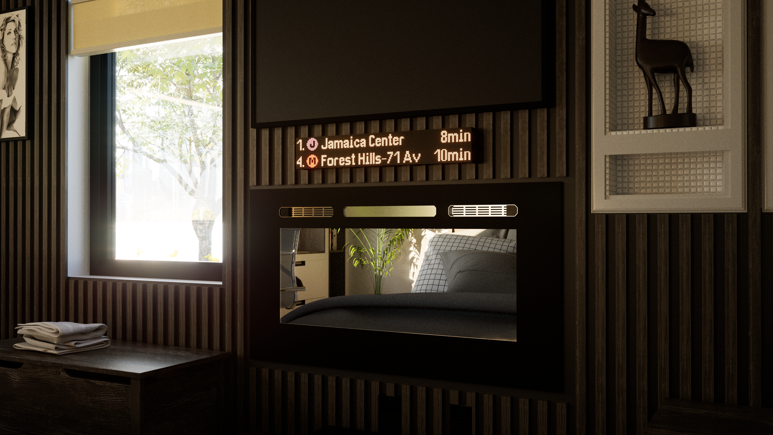
9) Mount your Finished Piece.
Once you have completed the previous steps, you can configure and mount your creation using the steps found in the latest manual here. This photo is an example of the 8-22mm Rear Mounting Kit applied to a 20”x30” laminated plywood engraving.